How Exhaust Gas Recirculation (EGR) system works
Updated: October 3, 2019
The Exhaust Gas Recirculation or EGR system is one of several vehicle emission control systems. It helps reduce the amount of the nitrogen oxides (NOx) in the exhaust gases. Nitrogen oxides are normally formed in the process of combustion in the engine cylinders.
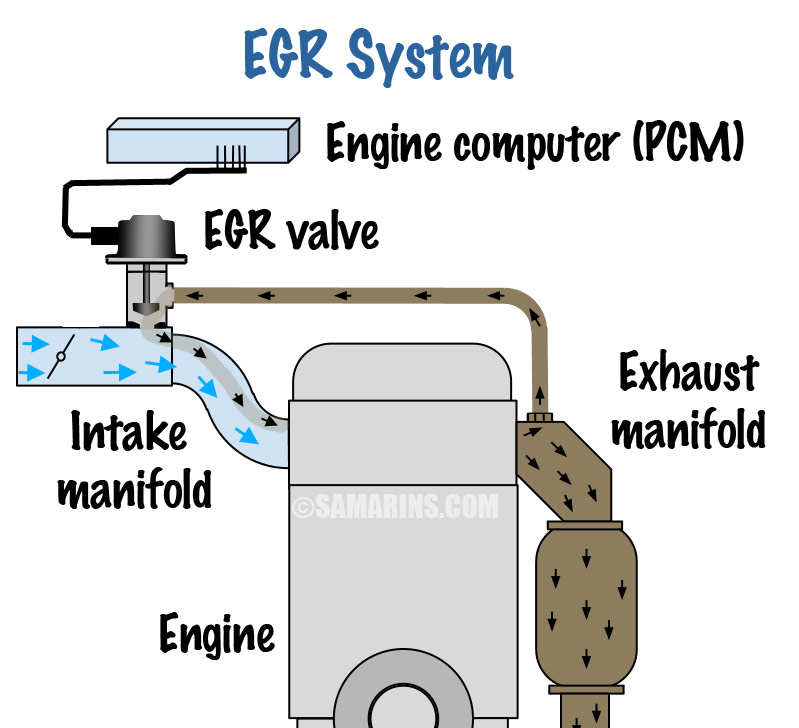 EGR system. Click for a larger image.
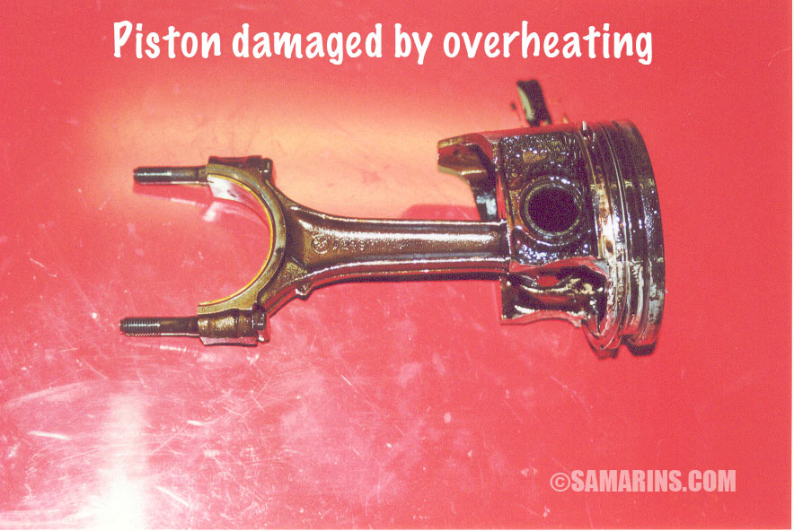
Higher combustion temperatures are also harmful to the engine. One of the effects caused by high combustion temperatures is a pre-ignition or detonation (pinging), when the air/fuel mixture ignites in the cylinders not from the spark, but from excessive heat. Because it happens at the wrong time, before the spark, the detonation adds strain on engine components. Prolonged detonation can damage the valves, pistons and other parts, see this photo. A turbocharger also fails sooner when exposed to excessive heat. The EGR system reduces the combustion temperature by diverting a small portion of the exhaust gases back into the intake manifold.
Not all vehicles are equipped with an EGR system; many newer cars utilize a variable valve timing and other means to control the combustion temperatures and NOx emissions.
How the engine computer or PCM controls the EGR system flow: The engine computer (PCM) opens or closes the EGR valve to control the flow within the EGR system. The EGR valve connects the exhaust manifold to the intake manifold.
 EGR system diagram
 In some cars, the EGR valve is operated by a vacuum actuator, as in the first diagram below. Modern cars have an electric EGR valve with a step motor. Read more about the EGR valve.
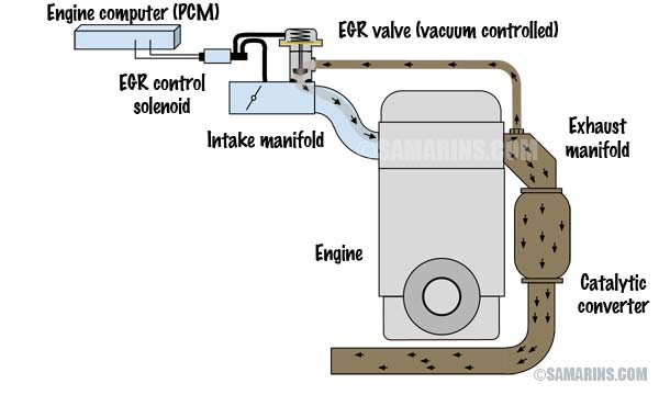
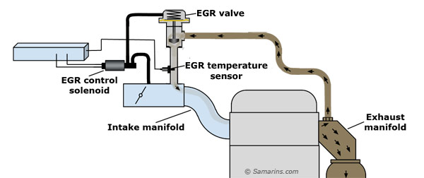 1: EGR system with a vacuum EGR valve and EGR temperature sensor
 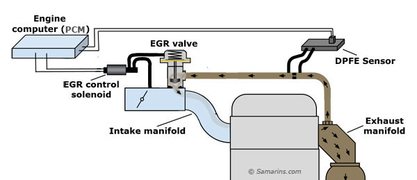 2: EGR system with a vacuum EGR valve and DPFE sensor
 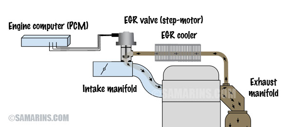 3: EGR system with an electric (step motor) EGR valve and EGR cooler
There are different ways to monitor the EGR flow. Some cars use an EGR temperature sensor installed in the intake part of the EGR system. When the EGR valve opens, the temperature on the intake side rises from the hot exhaust gases (diagram1).
Older Ford vehicles used a DPFE sensor (DPFE stands for Delta Pressure Feedback EGR) that measures the EGR flow based on the difference in pressure on both sides of the metered orifice in the exhaust part of the EGR system (diagram 2).
Modern cars use an electric EGR valve (diagram 3). Some cars also have an EGR cooler. The PCM controls the EGR flow by opening or closing the EGR valve with a step motor. The EGR flow is monitored by the manifold absolute pressure (MAP) sensor, mass air flow sensor and the air/fuel ratio sensor.