Disc Brake Diagram
Updated: October 17, 2022
How disc brakes work: Check out the diagram; it shows the disc brake layout with a floating caliper, which is the most common design in modern cars. The brake disc or 'rotor' (the green part) is installed on the hub. The wheel (not shown here) is installed on the same hub. The brake disc rotates together with the wheel. 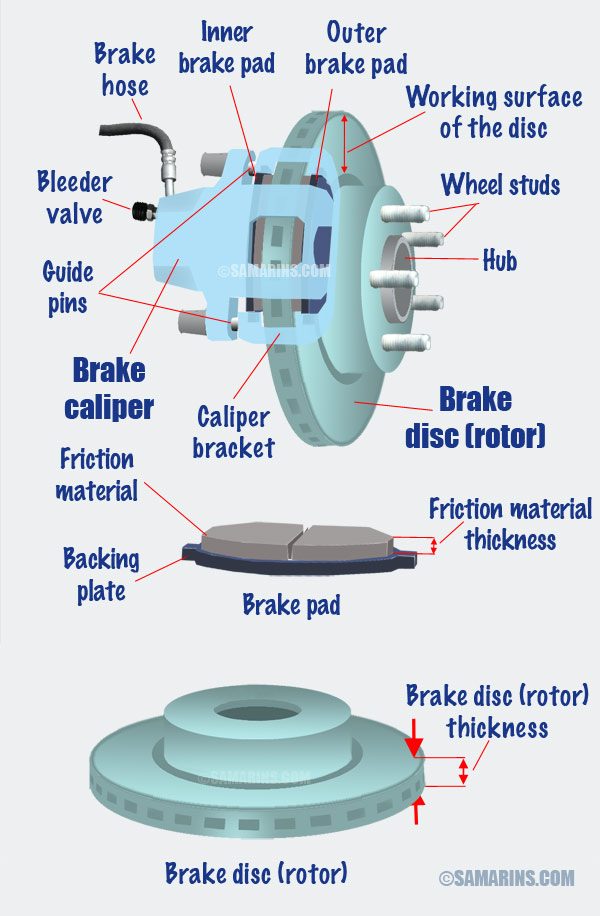 Disc brake diagram. Larger image.
The brake caliper (the blue part) is stationary. On the front wheels, the brake caliper bracket is bolted to the steering knuckle. On the rear wheels, the caliper bracket is secured to the rear axle or spindle. The brake caliper can slide laterally against the caliper bracket on two guide pins.
Two brake pads, inner and outer, are installed within the bracket on both sides of the rotor. Brake pads can also slide laterally (towards and away from the disc) on the bracket.
When the driver presses the brake pedal, the brake master cylinder attached to the brake pedal creates the pressure within the hydraulic braking system. The braking system transfers the brake fluid pressure through lines and hoses to the brake calipers at each wheel.
The caliper has one or two pistons. Under pressure, the piston extends and pushes the inner brake pad towards the brake disc. The reciprocal force pushes the caliper sway from the disc and the outer end of the caliper pushes the outer pad towards the disc.
As a result, the inner and outer brake pads squeeze the brake rotor between them. This clamping force slows the rotation of the disc (and the wheel) or stops it completely. The kinetic energy of the moving car transforms into heat. Most front brake rotors are ventilated to better dissipate the heat.
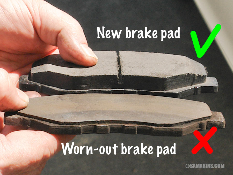 New and worn-out brake pads.
 When you bring your car for a service that includes a brake inspection, among other things, mechanics check the thickness of the pad friction material and the condition of the brake rotor including its thickness (see the diagram). Brakes are typically replaced when the pad friction material thickness gets too low as in this photo.
Old brake pads and discs are often worn unevenly, with grooves and ridges. New brake pads are flat.
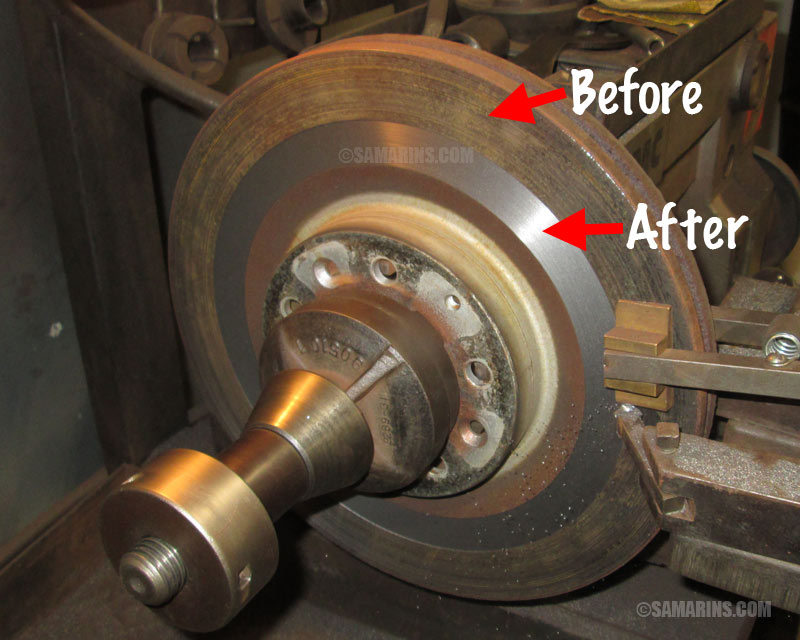 Machining of the brake disc on the brake lathe.
 To resurface or 'machine' the discs mechanics use a brake lathe, a machine that can cut thin layers of metal from both sides of the brake disc working surfaces to make them flat and uniformed. Some shops have portable brake lathes (on-car lathe) that can resurface brake discs without removing them from the car.
Resurfacing versus Replacing the brake discs:
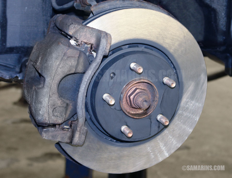 New OEM brake disc installed with new pads
If the new discs are too expensive or not readily available, resurfacing the old discs is a money-saving option. Brake discs can only be resurfaced if they have enough metal to meet the minimum thickness specifications provided by car manufacturers.